WO 2018092027: CONTROL SYSTEM FOR ASSISTING AN INTERNAL COMBUSTION ENGINE
Status
An objection was raised by Indonesian and European patent offices and the following was provided to the patent agent. Other application numbers for the same patent application are PCT/IB2017/057120 and 201641038845.
Supporting documentation
US20100071973: Komatsu
https://home.komatsu/en/company/tech-innovation/report/pdf/166-E05.pdf
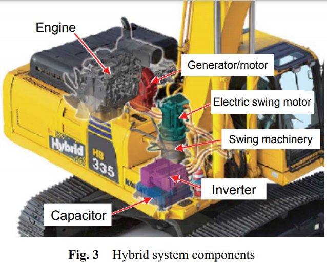
Komatsu’s patent has few key components – engine, generator motor, swing motor. To accelerate the engine quickly to the required speed from very low idle speeds (para74, also refer the link at the top of this document), torque assist is used.
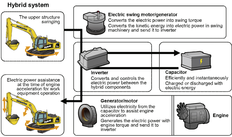
The generator motor can also provide torque assist to the engine. Para-74 of their patent specifically talks about low-speed operation of the engine to be supported by this operation. Given the description and the figure 3, their boost operation is fixed scaling up. Any voltage higher than what the motor can handle results in a maximum cap on the assist torque as given in figure 6. This torque assist is specifically given to ensure that the hydraulic pump’s efficiency is high, i.e. the engine’s speed is above a particular threshold. To accelerate the engine quickly to the required speed from very low idle speeds (para74, also refer the link at the top of this document), torque assist is used.
The background is that the hydraulic pump is at its best efficiency at a certain high speed of the engine. As seen in para75, the controller identifies the speed required, and the current speed; it calculates the assist torque required for acceleration by applying a basic and classical control method – Proportional controller. This assist torque requirement may not be fully supplied by the capacitor (even after the booster) if the voltage is lower than a threshold, vcap4. Based on the available capacitor voltage (above vcap3), the available assist torque is calculated (this happens to be the min of itself and the required assist torque) and applied by the generator motor.
Their inventive step is the assist by the generator motor so that the engine accelerates quickly to provide enough hydraulic power for rest of the vehicle operations.
(They charge the capacitor when the swing structure uses the swing brake during deceleration. Swing operation is the rotation of upper body about vertical axis, as shown in the first figure. )
Their claim 1 only talks about the method of calculating the possible assist torque. Their claim 8 includes capacitor voltage measurement setup, and also talks about finding the possible assist torque value.
WO2018092027A1 is operating with supporting the engine with the torque from the ISG motor at higher speeds. These support-speeds are well beyond the standard designed speeds of the motor at the battery voltage.
WO2018092027A1 claim 1 preamble says “…during and after starting and during high speed operations,…”,”…high speed operations and high throttle positions…”
WO2018092027A1 senses speed of the motor, torque from the motor, and the throttle positions. The highlighted ones are not available in their patent.
WO2018092027A1 claim 1 clearly says: if one of engine {torque, speed} is higher than corresponding threshold, boost circuit is triggered and the electrical motor’s supplied voltage is increased to limit the engine’s torque below a threshold.
In WO 2018092027A1, para 18 talks about controller for the electrical machine with a boost circuit to increase the available battery voltage. Para 21 talks about sufficiently increasing the voltage to the motor to produce the torque. The motor would not have been able to produce this torque without the boost operation. WO2018092027A1 also mentioned about passing a message to the engine controller to reduce the torque output correspondingly.
WO2018092027A1 is trying to reduce the engine’s operating torque to below a threshold, while their patent tries to increase the engine torque. WO2018092027A1 is trying to assist the engine at higher speeds for reducing the emissions, while they are trying to assist their engine at lower speeds so that their hydraulic system doesn’t consume too much energy – they are trying to increase fuel efficiency (para 74). They are not worried about the engine’s torque output at that operating point. They are only looking at the engine’s speed and the required speed to find the assist torque required. WO2018092027A1 has an additional element that is required for operating WO2018092027A1's system to reduce the emissions.
Let’s call D2: WO 2011/033528 A2 : KPIT Cummins
Their claims discuss about the location of the motor that assists the engine.
But their patent’s description text (paragraph 6) talks about operating the motor at a torque higher than rated continuous torque.
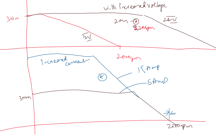
The top half of the graph shows what the inventors are doing in WO2018092027A1. The bottom half is what they are doing. Increased voltage to the motor controller results in increased operating speed – so the probable operating points are covered by the new motor curve. In their patent, they are increasing the torque by increasing the current into the motor. To some extent, both the results are same, but are achieved by using different motor designs. WO2018092027A1 motor can be designed as low-speed & high-torque motor that is most suitable for providing highest possible starting torque. When WO2018092027A1 is required to assist the engine, WO2018092027A1 will increase the operating speed of the motor by increasing the motor’s voltage. Their motor has to be originally designed to be a high speed motor – needs to cover all the operating speeds of the engine. Such a motor will have low turns on the stator, and low magnet count on the rotor. This requires a very high current to be pumped through the motor if one wants to use it for starting operation. WO2018092027A1's motor being a high torque motor has high magnet count on the rotor, and high winding turns on the stator.
Their text doesn’t show that the motor is intended for starting operation. Their text doesn’t show that their motor is used in combination with the voltage boost circuit.
D2 talks about a method of assisting IC engine for the emission control. However, they do not have any specific circuit arrangement for controlling the motor. In claim 1, they specify “…selectively operating the motor to provide assistance to the engine…”, and “…the motor is operated at a higher torque than a continuous operating torque rating of the motor…”. Any electric motor generally has a continuous operating torque (at which the motor can be run continuously- the heat energy generated in the motor can completely be dissipated or conducted or convected to maintain a constant steady state temperature of the motor parts) and the peak torque ( at the electromagnetic extremes of the motor – the heat energy generated is too high compared to the heat that can be taken out to arrive at a steady state temperature). The peak torque is generally a rating for 3 minutes or 30 seconds depending on the application and the manufacturers’ choice. Every motor will have a peak torque generally higher than the short term operable peak torque. D2’s choice of peak torque application to assist the engine is a natural behavior of the motor. The peak torque can be obtained from the motor just by pumping a specific current, higher than the continuous operating current. Additionally, every motor will have a rotational speed limit till which the maximum torque can be obtained. Beyond this speed limit, the back-emf voltage will be limiting the amount of current that can be pumped into the motor, thereby limiting the maximum torque that can be obtained. For the D2 to be functional for all the engine speeds for reducing the emissions, the motor needs to have the peak torque available till the maximum engine rpm. To design a motor of this maximum speed range, and also provide a considerable supporting torque, the amount of copper that has to be in the motor will be huge (to reduce the losses and to make the motor’s phase resistance low enough to accept the current for outputting the expected torque).
To avoid this limitation, WO2018092027A1 patent talks about a small motor design that can support the torque required for starting the motor and low motoring speeds under normal conditions. However, to support the torque assist at speeds beyond the normal motoring speeds of that motor, a higher voltage is applied from the voltage boost circuit so that inspite of the back-emf trying to oppose the current that WO2018092027A1 want to pump into the motor, WO2018092027A1 will be applying voltage higher than the back-emf on the motor coils at the given engine’s operating speed (same as motor’s speed) to facilitate the current go through the motor’s coils. The torque output from the motor is proportional to the current through the motor, WO2018092027A1 gets torque output from the motor. The inventive step is the inclusion of the voltage boost circuit and operating it to provide enough output voltage to provide the sufficient voltage to the motor so that the required torque gets generated. This required torque from the motor lets the engine’s output torque be maintained at most optimum point for the lowest emissions. The emission sensors included will help implement a control loop to increase or reduce the amount of torque assist to be provided to the engine. The total output torque thus gets shared between the engine and the assist motor. Instead of designing a bulky motor that has standard operating ranges covering entire engine’s speeds, WO2018092027A1 patent cleverly makes a small motor assist the engine at speeds that the motor can not operate at under normal conditions, by the voltage boost circuit and the corresponding method of control of the boost circuit so that the motor can provide torque at higher speeds than the designed motoring speeds (as explained earlier in this paragraph).
D2 talks about only the torque control of the motor, and doesn’t mention about the speed of the motor. WO2018092027A1 patent talks about measuring the speed & torque of the engine, and the throttle inputs to determine the required torque assist by looking at the emission values or from the known emission values at a given engine and speed values from the memory.
D2 has no additional circuit elements. WO2018092027A1 patent has voltage boost circuit and the method of controlling it helping it achieve emission reduction with a small motor. D2’s implementation requires a motor with a high speed capability and the high torque capability at the same time. Or, D2 may be limited to a very narrow speed band for emission control during the low engine speeds only. WO2018092027A1 patent can control emissions from the engine from the full range of the engine’s operating points. This helps more effective emission reduction with WO2018092027A1 implementation.
let’s call D4: US20100071971A1: Toyota Jidosha Et al.
D4 specifically talks about the motor with field coils in the claim1’s preamble “…including a field winding and having a field pole formed by a field current passing through the said field winding…”, whereas WO2018092027A1 patent talks about the motor with permanent magnets in the claim 1,”…including a rotor having a plurality of permanent magnets that are facing the plurality of teeth…”.
D4 didn’t talk about engine assist operation. D4 talks about the hybrid vehicles where the power output from the motor is used for the traction of the vehicle. Para 120 of D4 talks about “…electric motor 10 is a drive motor for generating the torque for driving drive wheels of a hybrid vehicle or an electric vehicle…”. WO2018092027A1 patent specifies that the motor is to be used for engine assist, and not as a traction motor, and that the peak torque is limited to 50 Nm in the claim 12. The same is elaborated in the para 25. Additionally, the para 25 also states that “…the peak torque at operating current of the electrical machine of the present invention is less than the operational requirement of a traction motor of a hybrid and/or electric vehicle…”.
D4 uses the voltage boost circuit that includes the field coil of the rotor as the inductor of the circuit for switching the boost circuit, as shown in figure 6. This implementation has few drawbacks. As the operation of the boost circuit commences, the inductor current is prone to oscillate. The inductor current increases from the minimum value, when the switching elements connect the inductor in line with the power source. The inductor current reduces from the maximum value when the inductor is disconnected from the power source, and let to free wheel through the diodes of the circuit. This causes the magnetic field in the rotor, as formed by the field current, to oscillate between a maximum and a minimum. The resulting flux linkage between the stator and the rotor also changes, causing pulsating torque output even at an expected steady-state operation. The end-result is a non-constant torque at wheels that makes the user feel as if the torque is increased and reduced. This may be equivalent to an uncomfortable jerky motion for the end-user. This effect is even more prominent at the discontinuous conduction mode of the voltage boost operation. This is the operation where the current levels are expected to be low, and for a brief time during the switching operation, the inductor current goes to zero. This results in no magnetic poles on the rotor, causing the loss of torque for the user. The end-result at low throttle input from the user is a very uncomfortable drive feel which actually applies the torque intermittently. Beyond the user feel, the pulsating torque also has detrimental effects on the mechanical parts along the drive-train. All the parts along the torque transfer path observe pulsating torque, and hence experience torsional oscillations. These oscillations increase fatigue of these parts and cause an early failure. The implementation of D4 by including the rotor field coil as the inductive element of the circuit has serious disadvantages.
WO2018092027A1 patent in figure 4 clearly indicates an independent inductor being used for the voltage boost operation, and this avoids all the problems associated with D4 such as the user discomfort and part failure due to fatigue. Including the voltage boost of such nature helps WO2018092027A1 patent achieve the torque assist at higher speeds of operation (beyond the normal motoring speeds that are possible when operating only on battery voltage). Such torque assist helps share the vehicle torque requirement and maintain the engine’s torque output for a given speed at an operating point that results in very low emissions. The implementation by WO2018092027A1 patent helps reduce the vehicular emissions.
WO 2006/125019 A2 : Maxwell technologies inc
The entire premise of the patent is centered on the use of double layered capacitor (super-capacitors or ultra-capacitors) which are known to support high discharge currents and charge currents. Regenerated energy is also said to be stored in the double layer capacitor module (para 11).
The patent describes the voltage boost circuit used in combination with the super-capacitors, and the whole combination is used to propel the vehicle in addition to the ic engine.
This patent doesn’t refer to emission reduction strategies, or any efforts to optimize the design of electric motors. The system is intended to be used at a single operating voltage, i.e. at the voltage that the voltage boost circuit provides.
The system arranges low voltage source and a voltage boost circuit so as to use the system as intended, as if the low voltage + voltage boost circuit is replaced by a higher voltage system.
WO2018092027A1 patent uses the same motor for three applications – starting the IC engine (a low voltage, low speed and high torque application – not described in the Maxwell patent application), generating the power from the ic engine , and assisting the ic engine at high speeds( a high voltage, high speed and medium torque application – not described in Maxwell patent application).
The Maxwell patent doesn’t describe the design that is required to make the same motor operate both at low speed and at high speed (Maxwell patent infers that any motor can be fitted irrespective of the design considerations, probably fails to explain the invention in full detail)- for example, 10Nm at 200-500 rpm and 3Nm at 4000rpm. If a single motor is to be designed for these two operating points, it needs to support a 10Nm peak torque and about 6000rpm (4000rpm at 3Nm, about 6000 rpm at about 0.1 Nm). This motor is going to be a bulky motor that requires both high current capability and high speed capability.
The maximum speed of the motor is proportional to the voltage and inversely proportional to the number of turns. To have higher maximum speed, while keeping the same voltage, the number of turns has to be made lower. This reduces the peak torque, if the current is maintained low.
The peak torque of the motor is proportional to the current and number of turns. If WO2018092027A1 increases the number of turns, the motor’s max speed comes down – because of increased back-emf. So, the motor needs to increase the current. To avoid the motor getting heated up (and getting damaged) due to the i2r (resistive) losses, the copper wire’s cross sectional area needs to be made larger. This makes the motor bulky and heavy. Such a motor reduces the fuel efficiency of the vehicle due to the added weight.
There is an interlinked relation between the number of turns, current, voltage, current of the motor with the peak torque, and the maximum speed. To have a motor that supports high speeds and high torque, the motor becomes bulky to support the higher extremities.
WO 2018092027A1:
WO2018092027A1 application is focused on emission reduction with the change of motor from ISG (integrated starter generator) to ISG+Power assist motor. TVSM patent’s motor is designed with storability as a primary target ( para 15) and it solves the problem of low speed range with the voltage boost.
Usually the voltage boost option is not used ( para 19). When the motr is not able to start the engine with the provided voltage, the voltage boost is used to produce higher torque. (para 19).
Question: Can the improvement in starting operation be used in the claim to limit the scope?
The voltage boost circuit also has a user input that may trigger voltage boost, in addition to the detection of engine’s condition that needs voltage boost (para 21) to provide assistance torque. This can be interpreted as not just automated operation for engine’s optimal operation, but probably through an input by the user (such as a switch operation ) in addition to the throttle operation. The motor controller also communicates with the engine controller to inform about the assist activation operation. This is different from the prior arts in such a way that the motor controller and the engine controller work together achieving the overall operation – lower emissions and assist torque.
Question: Can the user switch input be included in the claim to limit the scope?
The assist torque after user’s input (para 24, and para 29 a switch) is the torque assist that the user requests for a quick overtake, not just for a reduction in emission all the time.
Question: Can WO2018092027A1 reduce the 50Nm threshold to a lower limit that applies to two wheelers and three wheelers ( say about 15Nm threshold) to limit the scope?
Para 25 also says that the motor is only intended for an assist motor, not a standalone traction motor. This indicates that the motor is not rated for the continuous operation of the assist. This indicates that the motor is not designed to be a bulky motor that can operate at high speeds and high torques – resulting in increased weight, size and hence lower vehicle fuel efficiency.
Question: Can this reference to non-full-fledged operation as traction motor be included in the claim to limit the scope?
Question : Can claim 1 and 2 be clubbed together to include the user input switch as one of the inputs that controls the voltage boost?
Possible argument: WO2018092027A1 included a standard voltage boost, but the operation is controlled with inputs and the conditions.
• User input for additional acceleration
• Increased voltage for improved starting operation of the engine (when the engine is old, or on cold starting conditions, or when the battery voltage is low etc.)
• Engine condition monitoring to provide the torque assistance for emission reduction
The given voltage boost is not the only option, but one of the many possible options. But the conditions under which it is triggered and how it is utilized can establish inventive step.
Extended discussion:
reference to permanent magnets in the Toyota patent in paras 4,6,27,221 & 253:
4,6,221 are talking about the general permanent magnets in a motor, that will not work against us. i didn't see magnets mentioned in para 27
253 considers a case where the magnets are on the rotor, in addition to the coils. para 248 talks about a case - if a stronger field is required, the coil 50a and 50b are excited to support and increase the magnetic field. in the first case, where the q3 is used to create a constant flow of field current, we can say that the field is not constant, but oscillating between a max and min - depending on the current oscillation value. In the second case, where the field coil is used in addition to the magnets on the rotor, the field is constant under normal operations. But, in situations where the torque requirement is high, they turn the coil on - which means that the torque will oscillate again.
para 198 talks about independent operation of boost ckt and the field coil:
Good catch. 139 talks about one of the limitations that we initially assumed. 149-153 talks about Q3 where they are able to avoid the discontinuous conduction mode (DCM) that we discussed about ( in which the current goes to zero). Q4 is added to reduce the loss in the inductor. These inclusions address the limitations partly, but can not solve the problem of oscillating field current in the inductor - and hence the oscillating magnetic field strength. The increasing and reducing currents in the inductor are fundamental to the operation of the voltage boost circuit, also highlighted in 149 and 150.